When a project site faces 130 mph wind loads or snow accumulation exceeding 70 psf, standard roof mounts fail. This isn’t a matter of preference; it’s a structural liability. For challenging terrain or compromised roofs, **in-ground mounts** are the mandatory engineering solution where long-term durability is non-negotiable.
This technical brief examines the critical specifications for permanent mounting systems. We analyze the core components, from hot-dipped G165 galvanized steel posts to foundation requirements, and detail the mandatory compliance standards, including **ASCE 7** for minimum design loads and **UL 2703** for electrical bonding and grounding.
When to Choose In-Ground Mounting
In-ground mounting is for sites with open land or bad roofs, engineered for high wind (130 mph) and heavy snow (70+ psf) where roof mounts fail.
Roof mounts are the default for a reason—they’re usually cheaper and simpler. But when site conditions get tough, you have to go with an in-ground system. This isn’t about preference; it’s about meeting structural and environmental demands that a roof can’t handle.
High-Load Environments and Challenging Terrain
You switch to in-ground mounting when the site itself makes a rooftop installation impossible or unsafe. The primary drivers are weather and topography. If your project is in an area with extreme environmental loads or on a property with difficult ground, a ground mount is the only professional choice.
- High Wind Zones: Required for sites facing extreme wind, with systems engineered to withstand up to 130 mph.
- Heavy Snowfall: Necessary in regions where snow loads can hit 70 pounds per square foot (psf) or more.
- Sloped Properties: The only practical solution for sloped terrain, accommodating grades up to 10° North-South.
- Unsuitable Roofs: Used when the roof structure is too old, shaded, made of the wrong material, or simply too small for the required array size.

Engineered Foundations and Compliance Requirements
An in-ground system is a civil engineering project. It relies on a properly designed foundation and certified components to guarantee stability and meet strict building codes. The foundation isn’t an afterthought—it’s the core of the system’s resilience.
- Foundation Options: Systems use poured concrete footings in 12”–24” diameter holes or machine-installed ground screws, depending on soil conditions.
- Matériaux durables : Construction relies on corrosion-resistant components like hot-dipped galvanized steel posts (G165/G90) and 6000 Series Aluminum rails.
- Conformité au code : All designs must meet key structural and electrical standards, including ASCE 7 for minimum design loads and UL 2703 for proper grounding.
- Long-Term Warranty: Reputable systems are backed by a 20-year limited product and durability guarantee, ensuring long-term performance.
What Is In-Ground Mounting?
In-ground mounting embeds supports directly into soil via concrete, piles, or screws. This creates a durable, tiltable foundation engineered for high wind and snow loads.
Foundational Methods and Core Principles
In-ground solar mounting anchors an array directly to the earth using supports embedded in the soil, most commonly concrete footings, pile-driven steel posts, or ground screws. This approach creates a stable foundation without needing a large surface slab or ballast, which allows the array to be tilted for optimal energy production.
The foundations rely on durable materials to transfer structural loads into the ground. Common components include:
- Foundation Posts: Galvanized steel (G90 or ZAM275) or hot-dipped galvanized steel posts.
- Concrete Footings: Poured concrete in holes ranging from 12” to 24” in diameter, with embedded steel pipes.
Key Specifications and Compliance
Professionally engineered in-ground systems are designed to handle significant environmental stress and accommodate varied terrain. The key performance metrics and regulatory requirements include:
- Capacité de charge : Engineered to withstand wind speeds up to 130 mph and snow loads over 70 psf, in compliance with ASCE 7-16 standards.
- Adjustability: Often feature telescoping legs (e.g., adjustable from 24” to 101”) and fixed tilt angles (typically 15° to 35°) to handle sloped ground.
- Composants structurels : Use rigid materials like 6000 series aluminum rails to provide the core framework for the solar modules.
- Electrical Certification: Must be certified to standards like UL 2703 to ensure proper equipment bonding and grounding.
The Installation Process: An Overview
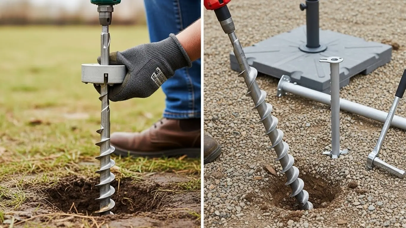
Installation hinges on two foundation methods: poured concrete footings for small jobs or machine-driven ground screws for larger sites, both meeting strict ASCE 7 load standards.
Foundation Methods: Concrete Footings vs. Ground Screws
The choice of foundation is a major decision point. Concrete footings are a traditional approach well-suited for smaller or DIY projects, while ground screws offer a faster, less disruptive option for larger-scale installations, provided the soil conditions are right.
- Concrete Footings: This method involves digging holes 12 to 24 inches in diameter and suspending a steel pipe in the center during the concrete pour. It’s a reliable choice for sites that don’t warrant a full geotechnical analysis.
- Ground Screws: For commercial sites, machine-drilled ground screws are installed based on an engineer’s soil evaluation. This approach eliminates the need for concrete, speeding up installation and reducing overall project costs.
Precision Assembly and Technical Specifications
Beyond the foundation, the structural integrity of the racking system depends on strict adherence to engineering specifications for materials, load capacity, and component dimensions. These systems are designed to perform under demanding environmental conditions.
- Capacité de charge : Engineered to withstand wind speeds up to 130 mph and snow loads of 70+ psf.
- Materials: Key components include 6000 Series Aluminum rails, hot-dipped galvanized steel posts (G165 or G90 specs), and 304 Stainless Steel hardware.
- Tilt & Terrain: Systems typically accommodate a 15°-35° tilt and can be installed on terrain with slopes up to 10° (North/South) and 5° (East/West).
- Conformité aux normes : Designs must meet codes like ASCE/SEI 7-10 for minimum design loads and UL 2703 for bonding and grounding.
Obtenez des prix directs d'usine sur les parapluies commerciaux personnalisés

Key Components: Pre-embed Sleeve and Flush Cap
A pre-embed sleeve creates a watertight passage through concrete. A flush cap protects this opening from deforming during the concrete pour.
| Component Feature | Spécification |
|---|---|
| Materials | Galvanized steel, stainless steel (V2A/V4A), or High-Density Polyethylene (HDPE) |
| Standard Diameters | ND 80 to ND 1000 (specialized FF variants from ND 50 to 500) |
| Waterproofing Features | Welded anchor flange (water-stop), circumferential grooves (mortar lock), textured outer surface (HDPE bond) |
| Compliance Standards | DIN 18533 (Waterproofing), DIN EN ISO 9001:2015 (Quality Management) |
Pre-embed Sleeve: Function and Waterproofing Design
The pre-embed sleeve’s job is to create a clean, pre-formed opening for pipes and cables in concrete foundations. Its design is all about preventing leaks. A welded-on anchor flange acts as a water-stop plate against both pressing and non-pressing water. Circumferential grooves lock into the installation mortar for a permanent seal. HDPE versions add a textured outer surface, creating a strong mechanical bond with the concrete to eliminate any potential leak paths.
Flush Cap: Materials, Sizing, and Compliance Standards
The flush cap is a simple but critical component. Its sole purpose is to protect the sleeve’s opening during the concrete pour. It prevents the sleeve from deforming under the weight and pressure of wet concrete and keeps the pathway clear of debris. This ensures the penetration point is perfectly formed, flush with the surface, and ready for use once the concrete sets.
Aesthetics & Durability: The Permanent Advantage
In-ground mounts use galvanized steel and aluminum to handle 130 mph winds and 70+ psf snow loads, ensuring longevity with a 20-25 year warranty.
| Spécification | Détails |
|---|---|
| Core Materials | 6000 Series Aluminum, Galvanized Steel (G90/G165/ZAM275), 304 Stainless Steel |
| Load Ratings | Wind: Up to 130 mph Snow: Up to 70+ psf |
| Compliance Standards | ASCE 7-16, UL 2703, AC428, California Building Code (CBC) 2013 |
| Manufacturer Warranty | 20-year limited product warranty, extendable to 25 years |
Engineered for Longevity: Core Materials and Design
In-ground mounts are chosen for sites where structural performance is non-negotiable. The material selection reflects this, focusing on corrosion resistance and strength to withstand decades of direct environmental exposure without the shelter of a roof structure.
- Primary Rails: 6000 Series Aluminum with a clear anodized or mill finish provides the core racking structure.
- Structural Posts: Schedule-40 steel pipe and mechanical tubing are used for the foundation legs, protected by G90, ZAM275, or G165 hot-dipped galvanized coatings.
- Hardware & Bonding: 304 Stainless Steel components and WEEB washers ensure secure connections and reliable electrical bonding that won’t degrade over time.
The design prioritizes function over form, but this results in a clean, industrial aesthetic. Standardized tilt angles between 15° and 35° optimize energy production, while the system’s adjustable legs can accommodate terrain with slopes up to 10° North-South. This inherent adaptability creates a visually consistent array, even on uneven ground.
Verified Performance: Load Ratings and Compliance
Performance claims for permanent infrastructure are useless without third-party validation. These systems are engineered and tested to meet specific building codes and safety standards, with PE-stamped reports available for most jurisdictions to simplify permitting.
- Wind Loads: Certified for wind speeds up to 130 mph.
- Snow Loads: Engineered to handle heavy accumulation, rated for 70+ psf.
- Core Standards: Compliant with ASCE 7-16 for minimum design loads and UL 2703 for electrical bonding and grounding safety.
- Warranty: Backed by a 20-year limited product warranty, with options to extend to 25 years, guaranteeing long-term structural integrity.
This level of compliance ensures the system is not just durable but also safe and insurable. It confirms that the mount can handle site-specific environmental forces as defined by the International Building Code (IBC) and local authorities.
Project Spotlight: High-Profile In-Ground Installations
In-ground solar mounts are engineered for extreme weather, handling 130+ mph winds and heavy snow. They use robust materials like galvanized steel, meeting strict ASCE and UL standards.
When a rooftop isn’t an option or the project demands maximum durability, in-ground systems are the go-to solution. These aren’t just posts in the ground; they’re pre-engineered structures designed to perform reliably in high-stress environments, from hurricane-prone coasts to heavy-snow regions.
Core Engineering for Extreme Weather Resilience
The structural integrity of these systems is validated against recognized engineering standards. This ensures they meet building codes and can handle site-specific environmental loads without failure.
- Wind Load Capacity: Engineered to withstand winds up to 130 mph (covering exposure categories B, C, and D).
- Snow Load Rating: Certified for conditions exceeding 70 psf (pounds per square foot).
- Key Compliance Standards: Adheres to ASCE 7-16, UL 2703 (for grounding and bonding), and holds a Category 1 structural rating.
- Terrain & Slope Tolerance: Designed to accommodate uneven ground, with a tolerance for up to a 10° N/S slope and a 5° E/W slope.
Material Specifications and Foundation Data
The system’s resilience comes from its components. Using galvanized steel and high-strength aluminum prevents corrosion and ensures a long service life with minimal maintenance. The foundation is equally critical, with options designed for different soil conditions and project scales.
- Matériaux du cadre : A combination of G90/G165 galvanized steel posts and 6000-series aluminum rails provides the ideal balance of strength and corrosion resistance.
- Adjustable Dimensions: Front legs adjust from 24″ to 51″, while rear telescoping legs can extend up to 101″ to accommodate sloped terrain.
- Matériel : Utilizes ¼”-20 stainless steel and 304 stainless steel hardware for secure, lasting connections.
- Ground Bonding: Certified to UL 2703 standards, requiring 14 AWG to 6 AWG copper conductors for electrical safety.
Foundation options range from traditional poured concrete footings to machine-driven ground screws, which can accelerate installation on larger sites by eliminating concrete work entirely.
Conclusion
In-ground mounting isn’t a preference; it’s a necessity. If your site has high wind, heavy snow, or an unsuitable roof, this is the only professional solution that meets engineering and code requirements.
Get a professional site assessment immediately. Confirm your roof’s structural limits and the site’s specific wind and snow loads to validate the need for an engineered in-ground foundation.
Foire aux questions
How do you install an in-ground umbrella mount?
To install an in-ground mount, you must dig a hole at least 18 inches deep, insert the anchor sleeve, and fill the hole with concrete to secure it. For cantilever systems, this may require up to 7 bags of quickset concrete. Allow the concrete to cure fully before inserting the umbrella.
Can I put a patio umbrella directly in the dirt?
Yes, you can install a parasol de terrasse in soil using specific in-ground mounts designed for dirt or clay. These systems typically feature a removable stem that anchors directly into the ground, securing 1.5” or 2” poles without needing concrete.
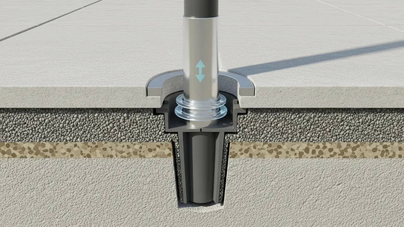
What is an in-ground umbrella sleeve?
An in-ground sleeve is a socket or receiver that is embedded in a concrete footing. It is designed to hold the umbrella pole securely, allowing for easy installation and removal of the umbrella while providing a permanent, stable base.
Are in-ground mounts better for high-wind conditions?
Not necessarily. Industry standards rate properly installed in-ground mounts and anchored surface mounts equivalently for wind resistance (up to 130-170 mph). The key to stabilité au vent is the depth of the concrete footing (12+ inches) and anchor specifications, rather than the mount type itself.