Specifying the right shade solution for a commercial project goes beyond picking a standard size from a catalog. When designs demand unique dimensions, custom shapes, or integration with existing architecture, off-the-shelf products fall short, creating coverage gaps and compromising the project’s vision.
This article breaks down the key technical aspects of custom sizing and space planning. We’ll cover how high-precision tube laser cutting achieves tolerances of ±0.1 mm for perfect fits and explore practical guidelines like the “2-Foot Rule” for optimal dining shade. We also discuss the engineering behind large-scale structures and the CAD support available to help architects validate layouts and clearances.
Custom vs. Standard: Factory Flexibility in Tube Cutting
Factories offer flexibility by using high-precision tube laser cutting for custom-length components, bypassing the constraints of standard pre-cut stock. This enables complex geometries and tight tolerances (typically ±0.1 mm to ±0.3 mm), allowing for unique, made-to-order designs that are impossible with traditional sawing or drilling methods.
| Specification | Laser Cutting Capability | Traditional Method Limitation |
|---|---|---|
| Dimensional Tolerance | ±0.1 mm to ±0.3 mm | Less precise; reliant on blade condition and manual setup |
| Geometric Complexity | High (integrated cuts, copes, slots, holes) | Requires multiple secondary operations (drilling, milling) |
| Material Handling | Raw tubes up to 12 meters; diameters up to 9 inches | Limited by pre-cut stock lengths and saw capacity |
Production Methods: Prefabricated vs. Custom Cut
Standard manufacturing often relies on prefabricated tube stock cut to common lengths. This approach restricts frame dimensions and usually requires secondary processes like drilling or milling to add connection points. In contrast, custom laser cutting works directly from raw tubing, which can be up to 12 meters long. This method provides complete design freedom, allowing for any length or complex geometry to be cut in a single operation. The process minimizes material waste and streamlines production by removing the need for extra steps, making it efficient for both simple custom sizes and intricate, CAD-driven designs.
Technical Tolerances and Material Capabilities
Modern tube laser cutters achieve dimensional tolerances between ±0.1 mm and ±0.3 mm, a significant improvement over traditional sawing. The technology handles a wide range of materials and tube diameters, from less than one inch to over nine inches. Advanced systems use touch-probes to measure the tube’s surface, automatically compensating for material imperfections like bowing or flexing. This ensures a high positioning accuracy of ≤0.03 mm. The laser creates a very clean cut with a minimal kerf (the width of material removed) of just 0.2 mm to 0.5 mm, preserving material integrity and producing parts ready for assembly.
The “2-Foot Rule”: Sizing Umbrellas for Dining Tables
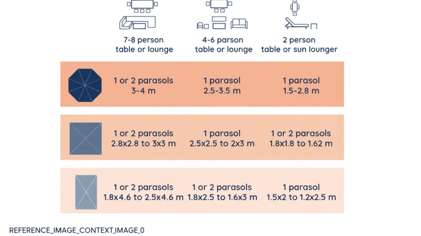
The “2-Foot Rule” is a guideline stating an umbrella canopy should extend at least 2 feet beyond the table’s edge on all sides. This means the umbrella’s diameter should be about 4 feet wider than the table to fully shade seated guests.
Core Principle: Ensure 2 Feet of Overhang on All Sides
The core guideline for sizing a dining umbrella is to ensure the canopy extends a minimum of two feet past the edge of the table on every side. This overhang accounts for the space taken up by chairs, making sure anyone seated at the table remains fully shaded from the sun. Following this rule means the ideal umbrella diameter will be approximately four feet wider than your table’s diameter or width, providing optimal coverage for everyone.
Matching Umbrella Diameter to Table Size
For small tables between 30 and 36 inches, an umbrella with a 6 to 8-foot diameter is generally suitable. Medium tables designed for four to six people (38 to 48 inches) should be paired with a 9 to 11-foot umbrella. Large tables measuring 54 to 60 inches require an 11-foot or larger umbrella to provide adequate shade for all guests.
The base weight must scale with the size of the canopy to ensure stability. An 8 to 9-foot umbrella needs a base weighing at least 50 pounds. For a larger 11-foot model, you should use a base that weighs a minimum of 75 pounds to prevent it from tipping over.
Engineering Giants: Reinforced Profiles for 13ft+ Structures
For structures over 13 feet, reinforced profiles use steel or Fiber-Reinforced Polymer (FRP) to manage high tensile stress and prevent cracking. Key specifications include minimum steel content of 0.7% in concrete, crack width limits under 0.02 inches, and high-performance FRP with structural safety factors ranging from 2.5 to 6.0.
Core Reinforcement Principles for Large Spans
Structures spanning over 13 feet (approximately 4 meters) require specialized reinforcement to handle high tensile stresses and flexural loads. A key objective is controlling crack widths, keeping them at or below 0.02 inches to ensure effective load transfer and protect internal steel from corrosion. These profiles also enhance durability against environmental factors; materials like pultruded Fiber-Reinforced Polymer (FRP) are particularly effective in corrosive or seismically active areas.
Material Specifications and Performance Metrics
Specific material standards are essential for performance. Steel-reinforced concrete requires a longitudinal steel content of 0.7% to 0.85% of the cross-sectional area, with a minimum concrete cover of 3.5 inches (89 mm) to prevent corrosion. For pultruded FRP profiles, specifications mandate a minimum fiber volume of 30% and a flame spread rating of 25 or less under ASTM E-84. Structural safety factors vary by application, from 2.5 for buildings up to 6.0 for critical infrastructure, to accommodate different load and environmental conditions.
Source Custom Commercial Umbrellas Direct from the Factory

For Architects: Providing CAD Blocks (DWG) & 3D Models
We provide architects with a range of standardized digital files to simplify space planning. This includes 2D DWG blocks for layouts and 3D models in formats like Revit (RVT) and SketchUp (SKP), all created at a low level of detail (LOD 100-200) for lightweight performance in early design phases.
Models for Space Planning and Layout Validation
Our CAD and BIM objects are designed as repeatable units, perfect for testing assignable square feet (ASF) metrics within your floor plans. The models use lightweight, space-planning geometry that is optimized for early-phase programming and test fits. This allows you to efficiently validate layouts against a Program of Requirements (POR) by using assets with accurate overall dimensions.
Supported File Formats and Industry Standards
To ensure seamless integration with your workflow, our digital assets adhere to common industry standards and are available in multiple formats. This approach guarantees compatibility with major architectural software and institutional project guidelines. The table below summarizes the key formats and technical specifications we support.
| Asset Type | Supported Formats | Technical Specifications |
|---|---|---|
| 2D CAD Blocks | DWG, DXF | Clean geometry adhering to AIA CAD Layer Guidelines or NCS v6. |
| 3D & BIM Models | RVT (Revit), SKP (SketchUp), IFC | Built to Level of Detail (LOD) 100–200 for efficient performance. |
| Embedded BIM Data | Integrated Parameters | Includes essential data such as Name, Area, and room-bounding geometry. |
Shape Molds: Manufacturing Square, Rectangle, and Octagon
Manufacturing molds for square, rectangle, or octagon profiles involves customizing steel inserts within standard mold bases, like DME A-series. The key factors ensuring quality are the steel grade (P20, H13, S7), hardness rating (up to 58 HRC), and adherence to SPI mold classifications for long-term production reliability.
Using Standard Mold Bases for Custom Shapes
Building a mold for a non-circular profile like a square, rectangle, or octagon doesn’t mean starting from scratch. Instead, manufacturers begin with a standard mold base, such as a DME A-series. They then engineer custom cavities and cores with the required geometry and fit them into this standard framework. This approach ensures the mold aligns with established factory specifications, including Society of the Plastics Industry (SPI) standard knock-out (KO) patterns for seamless integration with production presses.
Steel Selection and Hardness for Mold Longevity
The longevity of a production mold depends heavily on the material choices for its core components. High-wear cavities and cores are typically machined from hardened tool steels like H13, S7, or 420 stainless, which are heat-treated to a hardness of 48–58 HRC. To prevent galling and premature wear in sliding components, engineers maintain a hardness differential of 4 to 7 Rockwell C between the moving parts. For demanding, million-shot production runs (SPI Class 101), complex cores may also receive a nitride treatment that hardens the surface by 0.005–0.007 inches per side, significantly boosting durability.

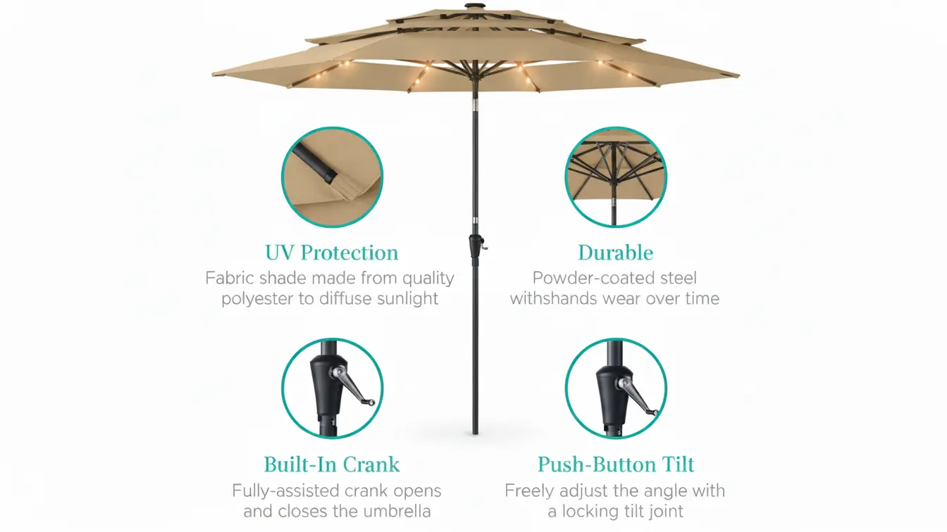
Clearance Planning: Accounting for Tilt and Rotation Arcs
Planning clearance for an umbrella means accounting for its full 3D motion. The arc created when the canopy tilts and rotates defines the true operational footprint, which is larger than its simple open diameter. This ensures the umbrella won’t hit walls, railings, or eaves during adjustment.
Defining the Motion Envelope: More Than Just Diameter
Tilt mechanisms alter the umbrella’s vertical and horizontal reach, lowering one side of the canopy while extending its profile.
Rotation features sweep the entire canopy in a circular path around the mast, requiring a clear radius free from obstructions like walls, columns, or other furniture.
The combined tilt and rotation arcs create a complete ‘motion envelope’ that must be clear to prevent damage and ensure safe operation.
Calculating Space Requirements for Key Movements
Specify the tilt range, which can extend from -5° to +7°, to determine the maximum vertical and horizontal displacement of the canopy edge.
Confirm the center of rotation and the canopy’s offset to map the precise path it follows, especially in models with 360-degree rotation.
Use manufacturer-provided drawings to simulate these arcs and verify clearance against architectural features before finalizing placement.
Wind Load Calculations: Engineering Bases for Large Sizes
Wind load calculations for large structures rely on engineering standards like ASCE 7-16. This process analyzes wind speed, structure height, and pressure coefficients to determine forces on the main frame (MWFRS) and its surfaces (C&C), ensuring stability in high-wind conditions.
Applying ASCE 7 Standards for Structural Integrity
All calculations are based on the ASCE 7-16 standard, the main guideline for figuring out wind loads on buildings and other structures. The analysis includes key factors like the basic wind speed for a specific location, such as 170 mph for high-risk areas, along with the structure’s height and its assigned Risk Category (I-IV). It also factors in terrain and exposure conditions to find the velocity pressure (qh) at the structure’s average height, a critical value used in load formulas.
Calculating Pressure on Main Frames and Components
The engineering method separates calculations for the Main Wind Force-Resisting System (MWFRS), which handles overall stability, from those for Components & Cladding (C&C), which addresses localized surface pressures. For structures under 60 feet tall, C&C loads are determined using specific formulas like P = qh [(GCp) – (GCpi)]. Engineers typically use a standard gust effect factor (G) of 0.85 for rigid structures and apply a minimum design wind load of 10 pounds per square foot (psf) to the MWFRS as a safety measure.
Final Thoughts
Creating the right shade solution goes far beyond picking a standard size from a catalog. Success depends on understanding the technical details, from the precision of laser-cut components to the engineering behind wind load calculations. Whether it’s selecting the right umbrella diameter with the “2-Foot Rule” or providing architects with precise CAD models, every step is about tailoring the product to the project’s specific needs. This integration of custom manufacturing and technical support ensures the final structure is not only functional but also perfectly suited to its environment.
Ultimately, this detailed approach to design and manufacturing bridges the gap between an architect’s vision and a structurally sound reality. Providing detailed CAD files, accounting for clearance arcs, and engineering reinforced profiles for large spans are not just extra services; they are essential parts of a successful project. This process ensures that every element fits, functions correctly, and stands up to its environmental demands, leading to a reliable and well-executed final installation.
Frequently Asked Questions
Can you make custom sizes that are not in your catalog?
Yes, we can produce custom tube sizes beyond catalog standards. Common ranges include outer diameters from 0.125″ to 6.000″, wall thicknesses from 0.030″ to 0.500″, and custom lengths, all governed by tolerances in ASTM A513 and A519 standards.
Do you provide CAD blocks or 3D models for architects?
Yes, providing downloadable CAD blocks (2D DWG/DXF) and 3D models (e.g., Revit, SketchUp, STEP/IGES) is a standard service for architects. These files are typically offered free of charge in multiple formats to integrate directly with common design software.
What is the largest commercial umbrella you can manufacture?
Specialized manufacturers produce giant commercial umbrellas spanning up to 30 meters (approximately 98 feet) in diameter, engineered for high wind loads and specific architectural projects. Other robust options for commercial shading can reach up to 20 feet in diameter.
How do I ensure the umbrella won’t hit guests when closing?
Keep guests at least 3-5 feet away from the umbrella during closing. The canopy and ribs collapse quickly via a spring-loaded mechanism. After pressing the button to fold the ribs, manually push the top and bottom ends together until you hear a “click” to confirm it is locked, making sure no one is in the path of the moving parts.