Wind pressure is unforgivingly non-linear; increasing wind speed from 10 mph to 70 mph amplifies the structural load by nearly 40-fold. Consequently, relying on standard commercial ratings of 40–59 mph for exposed sites invites catastrophic failure, whereas engineered supports are calculated to withstand shear forces at 115+ mph. This article dissects the physics of wind stability, contrasting static resistance against dynamic flexibility to determine optimal structural performance.
We break down the governing mechanics of load transfer, from the geotechnical application of Broms’ Method for center poles to the geometric nonlinear corrections required for flexible cantilevers. The analysis compares specific performance metrics—including Vestas V27 rotor modulation efficiency and ERCOT curtailment thresholds—while defining the critical gap between ASCE 7-22 survival standards and OSHA operational safety limits.
Introduction to Wind Dynamics
Wind dynamics uses power-law profiles and the Ekman spiral to model atmospheric boundary layer behavior, predicting structural loads and ensuring stability through calibrated safety indices.
Atmospheric Boundary Layer and Flow Profiles
Wind speeds do not remain constant; they increase with altitude within the atmospheric boundary layer (ABL). Engineers mathematically model this vertical gradient using power-law profiles. For flat surfaces characterized by horizontally homogeneous flow, the Ekman spiral defines both the rotation and magnitude of the wind vector.
Micrometeorological features control initial turbulence and flow stability. These baseline conditions dictate the aerodynamic structural response, making accurate site-specific profiling essential before calculating loads.
Computational Modeling and Design Standards
Computational Wind Engineering (CWE) solves discretized Navier-Stokes equations to manage turbulent flows and boundary conditions on structured or unstructured grids. To ensure structural reliability, engineers validate these simulations against specific industry protocols and theoretical models.
- ASCE 7 Standards: Use Database-Assisted Design (DAD) to interpolate directional wind speeds for specific eave heights and roof slopes.
- Design Protocols: Calibrate load factors against the safety index β to manage uncertainty in mean recurrence intervals.
- Blade Element Momentum (BEM): Incorporates Prandtl tip loss factors, axial induction control, and wake rotation for rotor aerodynamics.
- AeroDyn Models: Simulate dynamic stall (Leishman model), skewed flow, and tower shadow effects via potential flow around circular cylinders.
Static Stability: The Center Pole Approach
Stability relies on transferring lateral wind shear into the foundation via Broms’ Method. Commercial units rate 40–59 mph, while engineered supports withstand 115+ mph.
Mechanics of Load Transfer and Foundation Resistance
Center poles do not simply resist wind; they transfer lateral shear and overturning moments directly into the ground. Engineers calculate this resistance using Broms’ Method, which balances the horizontal wind load (Pa) at effective height against the foundation’s length (L) and diameter (D). The soil’s geotechnical properties determine whether the pole holds or the foundation rotates.
Material stiffness prevents the pole from snapping before the foundation fails. We rely on an elastic modulus of approximately 6,244,000 psi to limit deflection and rotation under service loads. Safety compliance follows strict buckling capacity rules per NESC standards:
- Standard Load Factor: 0.65 x nominal buckling capacity (Rule 250B).
- Extreme Wind Factor: 0.75 x nominal buckling capacity (Rule 250C).
- Foundation Geometry: Diameter is typically calculated at ⅔ of the burial depth (L).
Wind Speed Ratings and Critical Design Factors
A vast performance gap exists between standard commercial umbrellas and engineered structural poles. While heavy-duty signal supports withstand Strength Limit State speeds of 115 mph (33 psf) or 120 mph (36 psf) for Dynamic Message Signs (DMS), most commercial center-pole umbrellas max out at sustained gusts of 40–59 mph (95 kph). Exceeding these limits without guy wires invites immediate structural failure.
Calculating the Effective Projected Area (EPA) determines the precise limit for a given shape. Square or flat profiles generate significantly higher drag coefficients than round or airfoil shapes. Engineers validate these ratings using AASHTO 2013 and ASCE 7-05 criteria, which prioritize 3-second gust measurements taken at a height of 33 feet. The math incorporates a 1.14 gust factor to account for turbulence intensity in the atmospheric boundary layer.
Dynamic Flexibility: The Cantilever Approach
Flexible cantilevers require geometric nonlinear corrections to manage deflection, while strict adherence to uplift standards prevents buckling in spans exceeding pre-2004 design capacities.
Geometric Nonlinearity and Deflection Mechanics
Flexible elements, such as the IEA 15 MW wind turbine blade, do not behave linearly under load. Large deflections cause flapwise and edgewise bending to couple directly with torsion, which amplifies stress across the structure. Standard linear modal models fail to predict these secondary deflections accurately. You must use geometric nonlinear corrections, typically through solvers like HAWC2, to account for projected axial lengths and prebend effects properly.
While this dynamic flexibility allows structures to absorb significant wind energy, it introduces susceptibility to complex multi-axial forces. These forces diverge sharply from static load models, requiring advanced simulation to ensure structural integrity.

Wind Uplift Standards and Structural Stabilization
Uplift forces pose the primary threat to cantilevered stability. Standards like AS/NZS 1170.2 mandate higher wind coefficients for these roofs because older designs critically underestimated upward pressure. Consequently, pre-2004 structures often carry a 10 to 20 times higher risk of failure during serviceability wind events compared to modern equivalents.
Upward wind loading pushes top chords—specifically Circular Hollow Sections—and bottom flanges into compression. To prevent buckling, you must install lateral-torsional supports spaced according to CAN3-S136 l/r criteria. For large 21m spans, onsite welding presents safety hazards. The industry solution involves bespoke steel clamps and friction grip bolts, allowing for mid-span restraint and rapid stabilization without compromising the steel through heat.
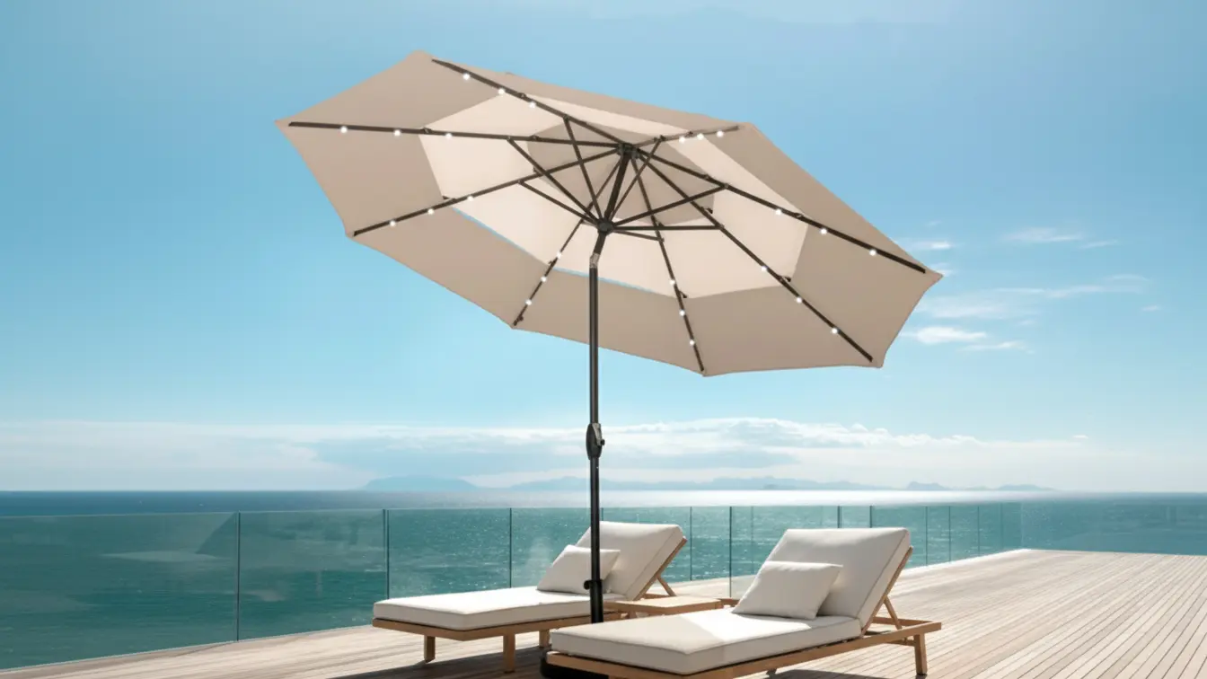
Source Commercial-Grade Umbrellas Direct from the Manufacturer

Stability vs. Flexibility: Performance Comparison
Rotor modulation delivers 6x the stored energy of synchronous generators with only 0.12% efficiency loss, while flexibility relies on UDMs to manage curtailment scenarios like ERCOT’s 2% threshold.
| Operational Metric | Stability Focus | Flexibility Focus |
|---|---|---|
| Control Mechanism | Rotor Speed Modulation (Vestas V27) | Steep Ramping & Deep Turn-downs |
| Performance Impact | 0.12% Efficiency Drop | 2% Assumed Curtailment (ERCOT) |
| Key Advantage | 6x Stored Energy vs. Synchronous Gens | Net Load Management |
| Modeling Requirement | Pacific DC Intertie Algorithms | User-Defined Models (UDMs) |
Operational Dynamics: Rotor Modulation and Grid Oscillations
Stability in wind energy relies on physical control mechanisms rather than passive generation. Vestas V27 turbines use rotor speed modulation to dampen inter-area oscillations, applying control algorithms originally derived from Pacific DC intertie tests. This approach allows the turbine to actively stabilize the grid frequency during disturbances.
The performance trade-off for this stability is minimal. Active power modulation decreases aerodynamic efficiency by only 0.12%, a negligible cost for the grid services provided. In return, these mechanisms deliver substantial inertia-like support:
- Stored Energy: Up to 6 times more energy per MW compared to conventional synchronous generators.
- Oscillation Damping: Proven reduction in transmission line instability using modified control loops.
- Efficiency Impact: 0.12% drop during active load balancing.
Modeling Accuracy and Flexibility Constraints
Flexibility deals with the net load—total demand minus wind output. This requires generators to handle steeper ramps and deeper turn-downs than baseload units. Operators often factor in inefficiencies to maintain this capability; for instance, ERCOT transmission optimization models assume a 2% wind curtailment rate to ensure system balance during high-variability events.
Accurate simulation is critical here. Standard Library Models (SLMs) frequently fail to capture dynamic behaviors during complex scenarios like MOD-026 tests. To predict performance accurately, engineers must use User-Defined Models (UDMs). These models are validated via hardware-in-the-loop (HiL) and field measurements to verify electromagnetic transient (EMT) accuracy and thermal stress handling during Fault Ride-Through (FRT) events.

Safety Guidelines: Managing Expectations in High Winds
Structural survival limits (105+ mph) differ vastly from operational safety limits. Cease active use at 20–30 mph to prevent injury and align with ANSI/OSHA benchmarks.
| Parameter | Survival Capacity (Structure) | Operational Limit (Safe Use) |
|---|---|---|
| Primary Goal | Prevent catastrophic collapse | Prevent user injury & liability |
| Wind Speed Reference | 105–130+ mph (ASCE 7-22) | 20–30 mph (OSHA/ANSI Proxies) |
| Typical Action | Permanent Anchoring | Close / Retract / Evacuate |
Structural Integrity vs. Operational Safety Limits
There is a critical engineering distinction between a structure’s ability to survive a storm and the conditions under which it is safe for human occupancy. We design structural systems under ASCE/SEI 7-22, which targets “Basic Wind Speeds” typically ranging from 105 to 130 mph (3-second gust at 33 ft) for a 50-year recurrence interval. These loads focus entirely on structural preservation, not user comfort.
Clients often mistake a “hurricane rating” for an “all-weather usage” guarantee. A product rated for 130 mph implies it will remain anchored and intact when closed and secured, not that it functions safely during the event. To account for unpredictable gusts on envelope systems, engineering standards recommend a minimum safety factor of 2, increasing to a safety factor of 3 for exterior-mounted anchorages. Survival capacity ensures the asset remains on the terrace; it does not authorize usage during high-velocity wind events.
Defining Safe Wind Thresholds and Protocols
Since specific “umbrella safety” codes do not exist, we adopt conservative cut-off limits from industrial construction standards. If a crane or scaffold cannot operate safely, a cantilever umbrella certainly cannot. Use these industrial proxies to set liability-proof operational protocols:
- Personnel Hoisting (OSHA 29 CFR 1926.1431): Operations must cease when winds exceed 20 mph. This is a strong baseline for closing large shade structures.
- Scaffolding (ANSI A10.8): Work is suspended when winds exceed 25 mph unless a competent person verifies safety.
- MEWPs (ANSI A92.22): Mobile elevating platforms are prohibited above 28 mph.
- High Wind Risk Eval (OSHA 29 CFR 1926.968): Winds exceeding 30–40 mph trigger a mandatory risk evaluation to secure all loose materials.
To manage user behavior, implement labeling that clearly distinguishes “Max In-Use Speed” (e.g., 20 mph) from “Max Survival Speed.” This prevents the dangerous assumption that a heavy-duty rating permits use during a gale.
Choosing the Right Shade for Your Environment
Wind pressure scales exponentially—a jump from 10 mph to 70 mph increases load nearly 40-fold. Site-specific engineering based on ASCE 7 standards is mandatory for structural survival.
Understanding Wind Loads and Code Requirements
Commercial shade structures must survive real-world forces, not just look good on a blueprint. You need to adhere to ASCE 7-22 and IBC Chapter 16 to determine the actual design wind speeds for your specific location. Most permanent frames require engineering for 100–115 mph survival ratings, while commercial fabrics are generally rated for >50 mph before they must be retracted or removed.
Wind pressure does not scale linearly. The physics are unforgiving and underscores why “eyeballing” a frame design leads to failure:
- Exponential Load Growth: Increasing wind speed from 10 mph to 70 mph jumps the load from roughly 0.25 lb/ft² to 10 lb/ft²—a 40× increase.
- Operational Limits: Warranties typically void if you fail to remove sails or retract awnings before gusts exceed design limits.
- Code Compliance: Local building codes adopt ASCE 7 wind maps to enforce minimum stability standards for sun-control structures.
Structural Geometry and Material Specifications
Your site’s exposure level dictates the shape you can safely build. Hip-end and sloped canopies are the superior choice for exposed, high-wind areas. Their aerodynamic profiles shed wind effectively, significantly reducing uplift forces on the anchors compared to flat or catchment shapes.
Cantilever structures are structurally inefficient in high wind. They act as sails, concentrating massive bending torque on a single column. You should restrict these to sheltered zones and ensure they are engineered with robust specifications:
- Reinforced Connections: Bolted or welded joints specifically designed to resist high uplift and torque.
- Material Grade: T6 aluminum or structural steel sections with sufficient wall thickness.
- Load Capacity: Verification for concentrated loads of 300 lb (snow/maintenance) in addition to wind pressure.
- Hardware: Stainless steel or zinc-plated bolts to prevent corrosion from becoming a failure point.
Final Thoughts
Survival ratings guarantee the steel holds, not that the asset is safe to use. In high-exposure zones, aesthetic flexibility becomes a liability trap; rigid stability is your only defense.
Enforce a strict “retract” protocol at 20 mph to eliminate injury risk. For permanent installs in open areas, reject cantilevers and specify aerodynamic hip-end shapes to reduce uplift.
Frequently Asked Questions
Are cantilever umbrellas good for high-wind conditions?
Cantilever umbrellas are not inherently wind-proof because of their offset design. However, commercial-grade models handle winds of 20-35 mph (Beaufort 5) effectively. For stability, you must select models with thick poles (minimum 0.07 inches/1.8 mm), integrated wind vents, and correct mounting hardware.
What features define the most wind-stable patio umbrella?
Stability relies on materials and weight. The best performers use marine-grade aluminum or fiberglass frames, solution-dyed acrylic canopies with vents, and heavy bases (typically 150 lbs+). Prioritize manufacturers that publish tested wind ratings, such as 38 mph limits or specific Beaufort scale certifications.
Why does my cantilever umbrella sway, and is it normal?
Swaying is a normal function that dissipates wind energy created by the side-offset mast’s long lever arm. However, excessive swaying usually indicates an under-weighted base. To minimize movement, follow the industry standard: 30-40 lbs of base weight per canopy foot (approximately 400 lbs for large units).
Do offset umbrellas blow over easily?
Not if they are weighted correctly. While the offset center of gravity creates a tipping risk, a quality umbrella paired with a 400 lb+ base or in-ground mount withstands Beaufort scale 8 winds (34-46 mph) without failing.